As the Surveyor Assistant-Major focus on site are: checking of road bed layers, fill layers, sub-grade layers, sub-base layers, base layers, priming, asphalt, culverts, cross-sections, benchmarks, reviewing longitudinal profiles design etc.
Road Bed Layer
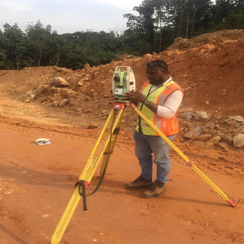
After the inspection/approval from the inspector, we captured/checked the natural ground levels, limits, dimensions, toe of slope using the total station. We always set out the Total station on the closest Benchmark, back sight on another Benchmark and coordinate them before we start to capture the Roadbed (RB) levels. We first pick the center point, offset 5.63, TOS LHS and RHS and natural ground of every 25m Chainage. We downloaded the data from the total station and give them to the inspector. Note: all cut sections are straightly Sub-grade layer levels.
Fill Layer
After the approval from the inspector, we captured the filled layers using the Leica NAK2 leveling machine and staff, and a tape rule to measure the 5.63 LHS and RHS from centerline of every 25m chainage. We set out the leveling machine properly, backsight on the closest benchmark, change point if necessary and begin to check the levels. After we have collected the data, we calculated and compared the actual filled levels with the Roadbed to know the thicknesses.
Sub-grade Layer
After the approval from the inspector, we captured the sub-grade layers using the Leica NAK2 leveling machine and staff, and a tape rule to measure the 5.63 LHS and RHS from centerline of every 25m chainage. We set out the leveling machine properly, back sight on the closest benchmark, change point if necessary and begin to check the levels. After we’ve collected the data, we calculated and compared the sub-grade actual levels with the sub-grade project design to get the difference; and also compared the sub-grade actual with the last filled layer actual to know the thicknesses.
Sub-base Layer
After the approval from the inspector, we captured the sub-base layers using the same Leica NAK2 leveling machine and staff, and a tape rule to measure the 5.26/5.33 LHS and RHS from centerline of every 25m chainage. We set out the leveling machine properly, back sight on the closest benchmark, change point if necessary and begin to check the levels. After the data has been collected, we calculated and compared the sub-base actual levels with the sub-base project design to get the difference and also compared the sub-base course actual with the sub-grade actual to know the thicknesses. To calculate the offset (5.26) from centerline for the sub-base layer, we first take the offset of the sub-grade layer minus the slope multiplied by the thickness (5.63-1.5 x 0.25 = 5.255).
Base Course Layer
After the approval from the inspector, we captured the base layers using the Leica NAK2 leveling machine and staff, and a tape rule to measure the 3.35 and 4.96 LHS and RHS from centerline of every 12.5m chainage. We set out the leveling machine properly, back sight on the closest benchmark, change point if necessary and begin to check the levels. After the data has been collected, we calculated and compared the base actual levels with the base course project design to get the difference and compare the base course actual with the sub-base actual to know the thicknesses. To calculate the offset (4.96) from centerline for the sub-base layer, we first take the offset of the sub-grade layer minus the slope multiplied by the thickness (5.26-1.5 x 0.20 = 4.96).
Prime Coat
We also gave the dimension /limit before priming is done.
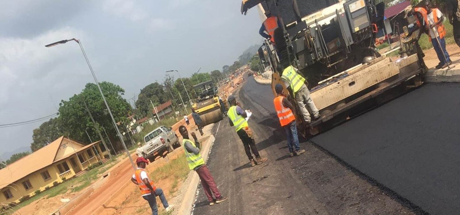
Asphalt Layer
We set out the centerline and mark/lined them on the top of the base course using the total station and paint before placing of the Asphalt. After the Asphalt layer has been placed, we checked the levels, dimension and thickness.
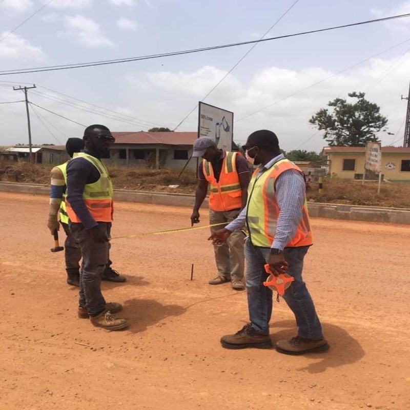
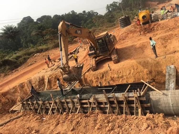
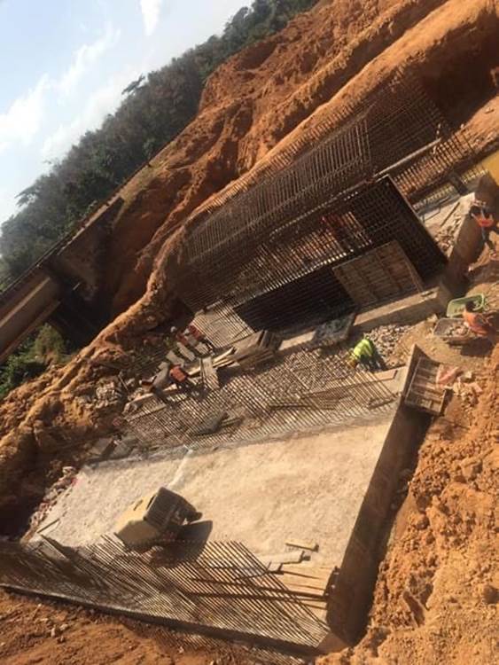
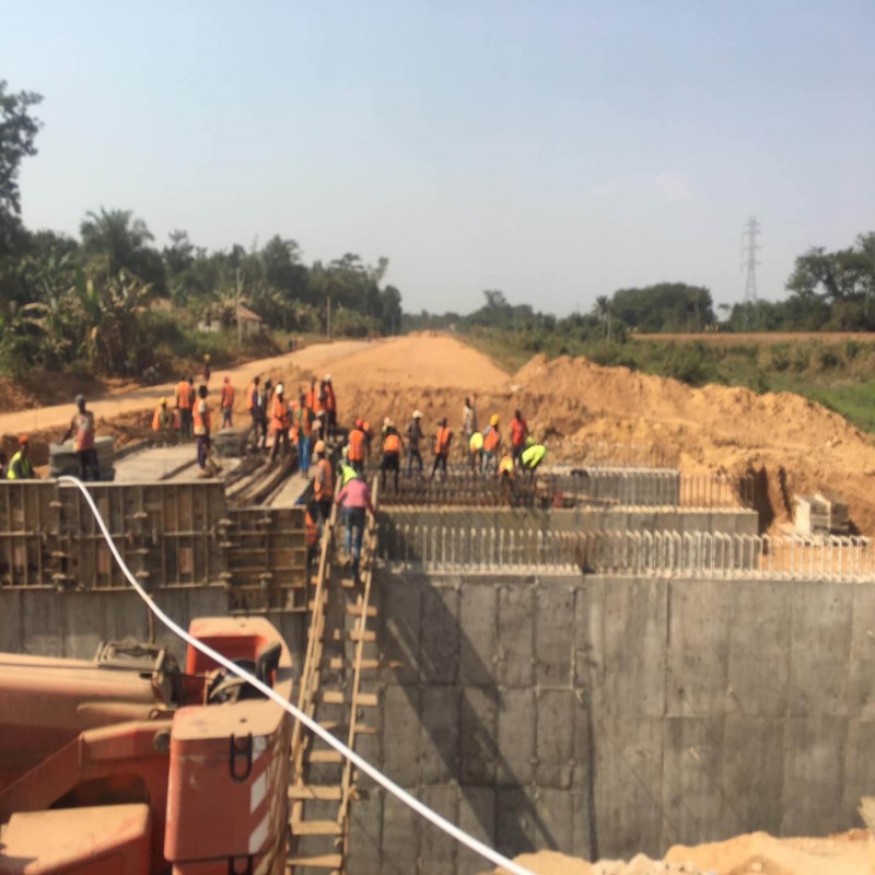
Culverts (Pipe and Box)
After the approval from the inspector, we and the contractor fix the centerline and laid out the culvert as per the design and put pegs to the various points. We fix the points using the total station and use the tape rule to measure the accurate dimension (length and weight) from centerline. While setting out the culvert, we always leave few meters away from the actual culvert and give levels for excavation. After excavation, we used the leveling machine and the culvert design to check the levels for the blinding concrete layer, after approval. After approval, we checked to verify the levels for the bedding concrete layer, setup by the contractor. We then verified the top slap levels set out by the contractor and fellow up with the entire culvert work until it is completed.
Cross-sections
We set out total station to capture the cross-section of rock, culvert, existing and propose road, etc. When taking cross-section of the road, we first capture the centerline, road edge, and natural ground.
Benchmarks
When verifying benchmarks, we set out the level machine, back sight on the closest benchmark, change point when necessary until we reached on another benchmark, step on that benchmark and continue to change point until I reach on another benchmark, step on that benchmark, return while repeating the same steps until we reach and close on the benchmark that I begin with. After we’ve collected the data, we found the misclosure of the benchmark. We also checked the benchmarks using Double station.